LEARNING OBJECTIVES
Upon completion of this module, the student will be able to:
1. Understand what wind mitigation is and why it is essential to structures in Florida
2. Identify the five wind mitigation techniques required for existing site-built, single-family residential structures constructed prior to 2002
3. Review gable-end bracing techniques and requirements
4. Review secondary water barriers installation requirements
5. Review roof to wall connections and roofing materials and attachments requirements
6. Review opening protections of windows, doors, sunlights, etc. requirements
Introduction
Wind mitigation specifically targets structural and nonstructural aspects to prevent or lessen damage caused by high winds and rain that may occur during storms. Here in Florida, the primary concern is wind and water damage caused by hurricanes. Hurricane season begins June 1 and ends November 30, which means that Floridians are at risk for exposure to hurricane force weather five months of the year. Also, it is not unusual to have a hurricane or tropical storm outside of hurricane season.
Wind mitigation activities include strengthening a structure by establishing a continuous load path, protecting and reinforcing openings such as doors and windows, and installing secondary water barriers.
In 2002, changes were incorporated into the Florida Building Code to 1) improve resistance of newly constructed homes to hurricane/wind damage and 2) to incorporate recognized wind damage mitigation techniques into existing site-built, single-family residential structures.
This course focuses on wind mitigation techniques to existing site-built, single-family residential structures. These wind mitigation methods are found in the Florida Statutes, Section 553.844: windstorm loss mitigation; requirements for roofs and opening protection.
There are five mitigation techniques in all,
• Gable-End Bracing
• Secondary Water Barriers
• Roof to Wall Connections
• Roof-Decking Attachments and Fasteners
• Opening Protections
Each technique is discussed in further detail, in the following sections.
GABLE-END BRACING
Gable-end bracing involves prescriptive methods for partial structural retrofit of an existing building to increase the resistance of gable end walls to out-of-plane wind loads.
| Note: It is intended for voluntary use and for reference by mitigation programs. The provisions of this section do not necessarily satisfy requirements for new construction. Unless specifically cited, the provisions of this chapter do not necessarily satisfy requirements for structural improvements triggered by addition, alteration, repair, change of occupancy, building relocation or other circumstances. |
The provisions of this section are applicable to buildings that meet all of the following eligibility requirements:
1. The building is occupancy Group R-3 (1-2 family dwellings).
2. The building includes one or more wood-framed gable end walls constructed using platform framing techniques.
3. The building shall have a mean roof height of 35 feet or less.
4. The building includes attic-framing members in the area where retrofit members will be installed shall be made of conventional lumber assembled with nails or the like or with truss plates.
5. The wall below a gable end wall being retrofitted shall be made of conventional lumber assembled with nails or the like, or with truss plates, or the wall shall be made of concrete or masonry.
6. Each gable end wall being retrofitted has or will be provided with studs or vertical webs spaced 24 inches on center maximum.
7. Each gable end wall being retrofitted has a maximum height of 16 feet.
8. The building is or would be assigned to risk category I or II in accordance with Table 1604.5(not shown here) in the Florida Building Code, Building.
9. The ceiling diaphragm of the retrofitted building in the area of the retrofit shall be comprised of minimum 1/2-inch gypsum board, minimum nominal 3/8-inch wood structural panels, or plaster.
10. The roof diaphragm of the building in the area of the retrofit shall be of minimum nominal 4-foot by 8-foot paneling made of plywood, oriented strand board, or similar, or boards butted to each other along their long edges and ends.
REQUIREMENTS
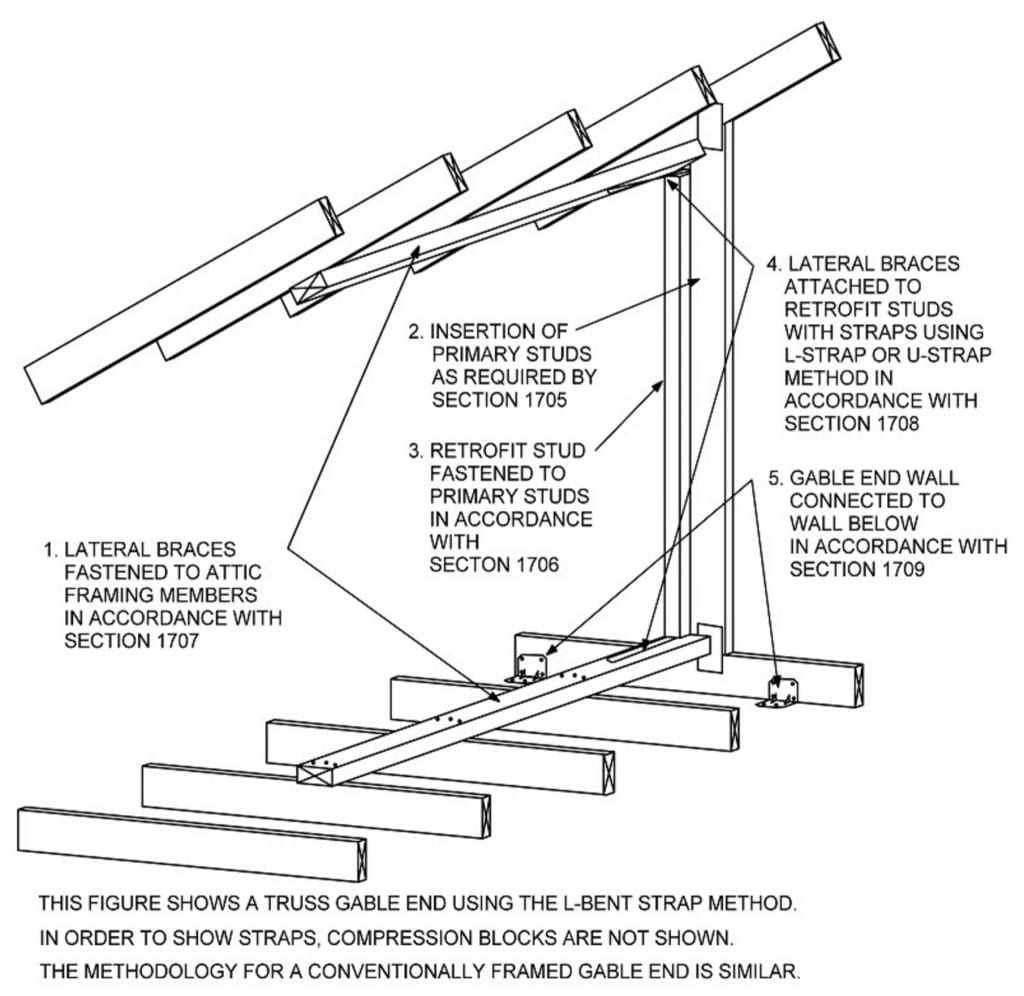
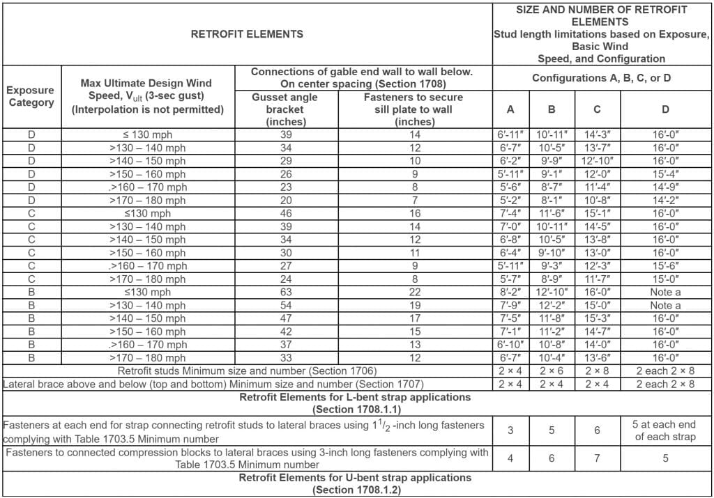
The strengthening scheme requires the installation of lateral braces, retrofit studs, and other load path components to supplement existing framing. Figure 1704.1 shows the general schematic arrangement of the various elements. Lateral braces and retrofit studs shall be installed at each primary stud as specified in sections 1706 and 1707 at each primary stud subject to strengthening, the retrofit configuration shall be determined in accordance with Table 1704.1. Retrofitting shall be in accordance with Section 1705 for installation of added studs where existing ones are too far apart; Section 1706 for the establishment of locations for retrofits and the installation of retrofit studs that strengthen primary studs; section 1707 for the installation of lateral braces that connect ceiling and roof diaphragms via attic-framing members; section 1708 for the two methods for the installation of straps that connect the ends of retrofit studs to lateral braces; and Section 1709 for connection of a gable end wall to the wall below.
Figure 1704.1 Gable-End Bracing – General Schematic Arrangement
1705 ADDED STUDS
1705.1 Requirements for added studs.
Along a platform framed gable end wall where an existing stud is longer than 3 feet and the distance (centerline to centerline) between that stud and an adjacent stud that is also longer than 3 feet is greater than 22 1/2 inches, an added stud shall be installed. This requirement also applies to the top truss of a piggyback truss assembly. The length of the stud shall be the maximum length of the stud itself exclusive of the depth of the top chord and bottom chord members. If an existing stud is interrupted by other members, such as by a diagonal in a truss with a gable end, it shall include retrofit stud sections above and below the interrupting member to provide continuity from the top of the bottom chord to the bottom of the top chord of the gable end framing, or wood structural members shall be added to provide this continuity. If a lateral brace is being omitted, as allowed in Section 1707.4.1, then the existing or added stud shall not be required to be continuous from an interruption to the location of the omitted lateral brace. Added studs shall have at minimum the same narrow and wide face dimensions as the existing studs.
Table 1703.5 Nail and Screw Requirements
Table 1704.1 Retrofit Configuration: Exposure Cat., Design Wind Speed, and Stud Height
1705.2 Placement of added studs.
Added studs shall be installed with the same orientation as existing studs. Added studs of piggyback trusses shall align with required primary studs in the truss below.
1705.3 Attachment of added studs.
In the case of conventional framing, each end of each required added stud shall be attached to the top and bottom plates. In the case of truss construction, each end of each required added stud shall be attached to the top and bottom chord of the truss. Attachments shall be made by attaching a stud-to-plate metal connector with minimum uplift capacity of 175 pounds fastened with 1 1/2 -inch long fasteners complying with Table 1703.5.
1705.4 Interrupted or short existing studs.
Existing studs longer than 3 feet that extend to only one end of attic framing members shall be retrofitted using the methods of Section 1706.6. Existing studs that are interrupted shall be retrofitted using the methods of Section 1706.7. 13-Hour Contractor Continuing Education 42
1706 RETROFIT STUDS
1706.1 Requirements for retrofit studs.
Except as allowed by Section 1706.5, a retrofit stud shall be installed at each primary stud longer than 3 feet where lateral braces can be installed using the methods of Section 1707. The size of retrofit studs shall be as required by Table 1704.1 (not shown here) for the appropriate retrofit configuration. Where straps are installed using the L-bent strap method of Section 1708.1.1, retrofit studs shall extend from the top of the lower lateral brace up to the bottom of the upper lateral brace, except that a maximum gap of 1/8 inch (3 mm), is allowed at the bottom and 1/2 inch at the top. Where straps are installed using the U-bent method of Section 1708.1.2, retrofit studs shall extend beyond the ends of lateral braces such that lateral braces can fully butt against the retrofit studs.
| Exception: A retrofit stud need not be added where the distance between it and an adjacent retrofit, primary stud would be less than 14 1/2 inches. |
1706.2 Piggyback trusses.
Primary studs of piggyback truss assemblies shall have retrofit studs sized and placed such that a single continuous retrofit stud is installed and fastened to the primary stud of both the lower and upper truss. Added studs shall be placed and fastened in accordance with Section 1705. The bottom chord of the upper truss shall be connected to the retrofit stud using an approved connector with minimum tension capacity of 175 pounds.
1706.3 Placement of retrofit studs.
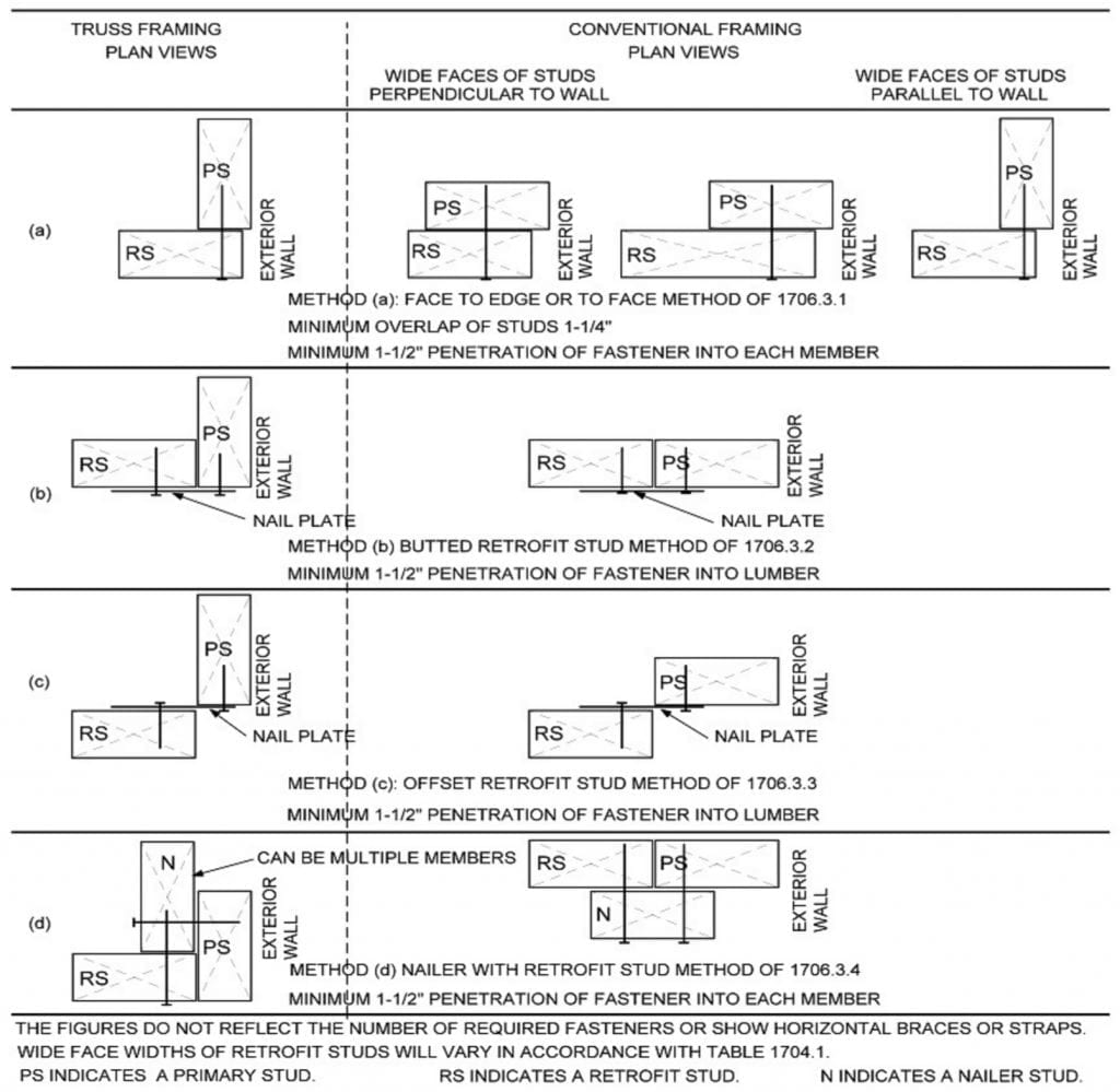
Retrofit studs and nailers can be placed on either side of primary studs. Retrofit studs shall be installed in accordance with one of the following methods: Code Sections 1706.3.1 through 1706.3.4 describe each of the four methods, reference Figure 1706.3.
The remainder of Section 1706 describes attachment and fastening methods for the retrofit studs as well as “work-around” techniques to deal with various existing conditions, such when a “ladder assembly” or spliced retrofit studs are allowed.
1707 LATERAL BRACES
1707.1 Requirements for lateral braces.
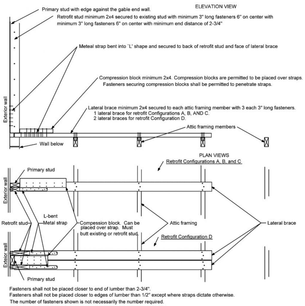
At each end of a retrofit stud, a lateral brace shall be installed as indicated in Figure 1707.1(1) (shown on following page) or Figure 1707.1(3) for trusses and Figure 1707.1(2) or Figure 1707.1(4) for conventionally framed gable end walls. Lateral braces shall be allowed to be omitted in accordance with Section 1706.6 or
1707.4.1. Alternative methods for providing lateral bracing are allowable in accordance with Section 1707.4. Lateral braces shall be minimum 2 × 4 lumber except as required by Section 1707.4.1 or Section 1706.6.
Figure 1706.3 Placement of Retrofit Studs
1707.2 Placement of Lateral Braces.
Lateral braces shall be placed approximately perpendicular to the attic-framing members and extend so they are attached to a minimum of three attic-framing members. The attic-framing member farthest from the gable end wall shall be a minimum of 6 feet from the exterior sheathing or siding on the gable end wall. Lateral braces shall be installed with their wide faces across attic framing members. Where the method of Section 1708.1.1 is used, lateral braces shall butt against the sheathing or siding of the wall. Where the method of Section 1708.1.2 is used, lateral braces shall butt against the retrofit studs.
| Exception: Where existing conditions prevent placement of continuous lateral braces on attic-framing members, installation shall be in accordance with Section 1707.4. |
Code Sections 1707.3 through 1707.3.3 describe attachment and fastening methods for the lateral braces. Sections 1707.4 through 1707.8 describe “work-around” techniques to deal with various existing conditions, such when outlookers exist or where existing conditions prevent installation of lateral braces near the peak of roofs.
1708 ATTACHMENT OF LATERAL BRACES TO RETROFIT STUDS
1708.1 Attachment of lateral braces to retrofit studs. The top and bottom of each retrofit stud shall be attached to a lateral brace with a minimum 11/4 inches (32 mm) wide approved flat or coil metal straps with pre-punched holes for 10d common or 16d common nails or #9 screws. No attachment is required for the retrofit stud located at an omitted lateral brace location where connectors are in place in accordance with Section 1707.4.1. Straps shall be fastened using the size and number of fasteners in accordance with Table 1704.1. For use of L-bent straps, attachment shall comply with the method of Section 1708.1.1 and for use of U-bent straps with the method of Section 1708.1.2. Either method is allowable at either end of a retrofit stud.
The remainder of Section 1708 describes the various methods of attaching lateral braces to retrofit studs.
Figure 1707.1(1) Truss Gable End Wall with L-Bent Straps
SECTION 1709 CONNECTIONS TO WALL BELOW
1709.1 Requirements.
Along gable ends where primary studs are longer than 3 feet (914 mm), gable end walls shall be connected to the wall below using the methods prescribed in Section 1709. 13-Hour Contractor Continuing Education 44
The remainder of Section 1709 describes the various methods to connect gable end walls to the wall below, including for truss gable end walls, wood frame walls below, concrete or masonry walls below, and platform framed gable end walls.
SECONDARY WATER BARRIERS
When a roof covering on an existing site-built single family residential structure is removed and replaced, the following procedures shall be permitted to be performed by the roofing contractor:
• Roof-decking attachment shall be as required by Section 708.7.1.
• A secondary water barrier shall be provided as required by Section 708.7.2.
| Exception: Single family residential structures permitted subject to the Florida Building Code are not required to comply with this section. |
REQUIREMENTS
708.7.2 Roof secondary water barrier for site-built single family residential structures.
A secondary water barrier shall be installed using one of the following methods when roof covering is removed and replaced:
1. In either HVHZ (High Velocity Hurricane Zone) or Non-HVHZ regions:
a) All joints in structural panel roof sheathing or decking shall be covered with a minimum 4-inch wide strip of self-adhering polymer modified bitumen tape applied directly to the sheathing or decking. The deck and self-adhering polymer modified bitumen tape shall be covered with one of the underlayment systems approved for the particular roof covering to be applied to the roof.
b) The entire roof deck shall be covered with an approved asphalt impregnated 30# felt underlayment or approved synthetic underlayment installed with nails and tin-tabs in accordance with Section 1518.2, 1518.3, or 1518.4 of the Florida Building Code, Building. (No additional underlayment shall be required over the top of this sheet.) The synthetic underlayment shall be fastened in accordance with the manufacturer’s recommendations.
2. Outside the HVHZ:
a) The entire roof deck shall be covered with an approved self-adhering polymer modified bitumen sheet meeting ASTM D 1970 or an approved self-adhering synthetic underlayment installed in accordance with the manufacturer’s installation instructions. No additional underlayment shall be required on top of this sheet for new installations.
b) An underlayment system approved for the particular roof covering shall be applied with the following modification:
(1) For roof slopes that require one layer of underlayment, a layer of approved asphalt impregnated ASTM D 226 Type I or Type II, ASTM D 4869, Type II or Type IV underlayment or approved synthetic underlayment shall be installed. The felt is to be fastened with 1-inch round plastic cap, metal cap nails or nails and tin-tabs attached to a nailable deck with two staggered rows in the field of the sheet with a maximum fastener spacing of 12-inches o.c. and one row at the overlaps fastened 6-inches o.c. Synthetic underlayment shall be fastened in accordance with this section and the manufacturer’s recommendations.
(2) F or roof slopes that require two layers of underlayment, an approved asphalt impregnated ASTM D 226 Type I or Type II, ASTM D 4869, Type II or Type IV underlayment shall be installed in a shingle fashion and lapped 19 inches and fastened with 1-inch round plastic cap, metal cap nails or nails and tin-tabs, attached to a nailable deck with one row in the field of the sheet with a maximum fastener spacing of 12-inches o.c. and one row at the overlaps fastened 6-inches o.c. An approved synthetic underlayment shall be installed in accordance with this section and the manufacturer’s installation instructions. (No additional underlayment shall be required over the top of this sheet).
Exceptions: 1. Roof slopes < 2:12 having a continuous roof system shall be deemed to comply with Section 708.7.2 requirements for a secondary water barrier. 2. Clay and concrete tile roof systems installed as required by the Florida Building Code are deemed to comply with the requirements of Section 708.7.2 for secondary water barriers. |
When a roof covering on an existing site-built single-family residential structure is removed and replaced on a building that is located in the wind-borne debris region as defined in the Florida Building Code, Building and that has an insured value of $300,000 or more or, if the building is uninsured or for which documentation of insured value is not presented, has a just valuation for the structure for purposes of ad valorem taxation of $300,000 or more:
(a) Roof to wall connections shall be improved as required by Section 708.8.1.
(b) Mandated retrofits of the roof-to-wall connection shall not be required beyond a 15-percent increase in the cost of reroofing.
ROOF TO WALL CONNECTIONS
708.8.1 Roof-to-wall connections for site-built single-family residential structures.
Where required by Section 708.8, the intersection of roof framing with the wall below shall provide sufficient resistance to meet the uplift loads specified in Table 708.8.1 (not shown here), either because of existing conditions or through retrofit measures. As an alternative to an engineered design, the prescriptive retrofit solutions provided in Sections 708.8.1.1 through 708.8.1.7 shall be accepted as meeting the mandated roof-to-wall retrofit requirements.
Exceptions: 1. Where it can be demonstrated (by code adoption date documentation and permit issuance date) that roof-to-wall connections and/or roof-to foundation continuous load path requirements were required at the time of original construction. 2. Roof-to-wall connections shall not be required unless evaluation and installation of connections at gable ends or all corners can be completed for 15 percent of the cost of roof replacement. |
The remainder of Section 708.8.1.1 through 708.8.1.7 describe the allowable methods obtaining access for retrofitting roof to wall connections, as well as the exact methods for installing and fastening straps depending on the style of roof and the wall construction below.
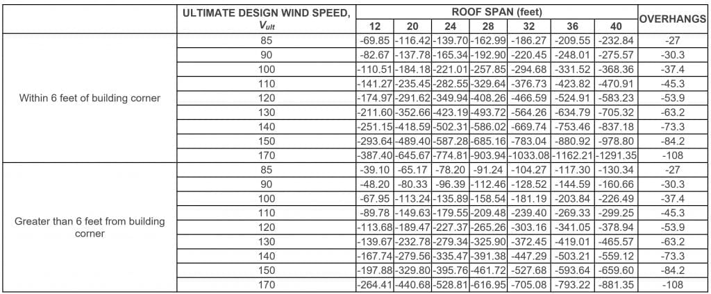
Table 708.8.1 Required Uplift Capacities for Roof-To-Wall Connections (Pounds per Linear Foot)
ROOF-DECKING ATTACHMENTS AND FASTENERS
706.3.2 Roof diaphragms resisting wind loads in high-wind regions.
Where roofing materials are removed from more than 50 percent of the roof diaphragm or section of a building located where the ultimate design wind speed, Vult, is greater than 115 mph, as defined in Section 1609 (the HVHZ shall comply with Section 1620) of the Florida Building Code, Building, roof diaphragms, connections of the roof diaphragm to roof framing members, and roof-to-wall connections shall be evaluated for the wind loads specified in the Florida Building Code, Building, including wind uplift. If the diaphragms and connections in their current condition are not capable of resisting at least 75 percent of those wind loads, they shall be replaced or strengthened in accordance with the loads specified in the Florida Building Code, Building.
708.7.1 Roof decking attachment for site-built single-family residential structures.
For site-built single family residential structures the fastening shall be in accordance with Section 708.7.1.1 or 708.7.1.2 as appropriate for the existing construction. 8d nails shall be a minimum of 0.113 inch in diameter and shall be a minimum of 2 1/4 inch long to qualify for the provisions of this section for existing nails regardless of head shape or head diameter.
708.7.1.1 Sawn lumber or wood planks:
Roof decking consisting of sawn lumber or wood planks up to 12 inches wide and secured with at least two nails (minimum size 8d) to each roof framing member it crosses shall be deemed to be sufficiently connected. Sawn lumber or wood plank decking secured with smaller fasteners than 8d nails or with fewer than two nails (minimum size 8d) to each framing member it crosses shall be deemed sufficiently connected if fasteners are added such that two clipped head, round head, or ring shank nails (minimum size 8d) are in place on each framing member it crosses.
Table 708.7.1.2 Supplement Fasteners at Panel Edges and Intermediate Framing
708.7.1.2 Wood structural panels:
For roof decking consisting of wood structural panels, fasteners and spacing required in columns 3 and 4 of Table 708.7.1.2 (not shown) are deemed to comply with the requirements of Section 706.3, Florida Building Code, Existing Building for the indicated design wind speed range. Wood structural panel connections retrofitted with a two part urethane based closed cell adhesive sprayed onto the joint between the sheathing and framing members are deemed to comply with the requirements of Section 706.3, Florida Building Code, Existing Building, provided testing using the manufacturer’s recommended application on panels connected with 6d smooth shank nails at no more than a 6-inch edge and 12-inch field spacing demonstrate an uplift resistance of a minimum of 200 psf.
Supplemental fasteners as required by Table 708.7.1.2 shall be 8d ring shank nails with round heads and the following minimum dimensions:
1. 0.113-inch nominal shank diameter.
2. Ring diameter a minimum of 0.010 inch over shank diameter.
3. 16 to 20 rings per inch.
4. A minimum 0.280-inch full round head diameter.
5. Ring shank to extend a minimum of 1 1/2 inches from the tip of the nail.
6. Minimum 2 3/8-inch nail length.
OPENING PROTECTIONS
706.4 Replacement of windows and doors.
The replacement of garage doors, exterior doors, skylight, operative and inoperative windows shall be designed and constructed to comply with Chapter 16 of the Florida Building Code, Building.
Exceptions: 1. Opening protection exception. For one- and two-family dwellings constructed under codes other than the Florida Building Code and located in windborne debris regions, the replacement of garage doors and exterior doors with glazing, sliding glass doors, glass patio doors, skylights, and operable and inoperable windows within any 12-month period shall not be required to have opening protection but shall be designed for wind pressures for enclosed buildings, provided the aggregate area of the glazing in the replaced components does not exceed 25 percent of the aggregate area of the glazed openings in the dwelling or dwelling unit. 2. Opening protection exception for High-Velocity Hurricane Zones. For one-and two-family dwellings constructed under codes prior to September 1, 1994, the replacement of exterior doors with glazing, sliding glass doors, glass patio doors, skylights, and operable and inoperable windows within any 12- month period shall not be required to have opening protection provided the aggregate area of the glazing in the replaced components does not exceed 25 percent of the aggregate area of the glazed openings in the dwelling or dwelling unit. |
706.5 Openings in sunrooms, enclosed balconies and enclosed porches:
Openings in sunrooms, enclosed balconies and enclosed porches constructed under existing roofs or decks are not required to be protected, provided the space is separated from the building interior by a wall and all openings in the separating wall are protected in accordance with Section 1609.1.2 of the Florida Building Code, Building. Such spaces shall be permitted to be designed as enclosed or partially enclosed. (High- Velocity Hurricane Zones must comply with Chapter 16 of the Florida Building Code, Building.)
Exceptions: 1. Exterior balconies or porches under existing roofs or decks enclosed with screen or removable vinyl and acrylic panels complying with the Florida Building Code, Building, Section 2002.3.3 shall not be required to be protected and openings in the wall separating the unit from the balcony or porch shall not be required to be protected unless required by other provisions of this code. 2. High-Velocity Hurricane Zones must comply with Chapter 16 of the Florida Building Code, Building. |
REFERENCES
FBC 5th Edition (2014) Existing Building, Ch. 7 Alterations-Level 1:
FBC 5th Edition (2014) Existing Building, Ch. 17 Retrofitting:

